Embedded systems prototype
SolarBot
Sensor-driven solar tracking system combining embedded control, environmental sensing, telemetry, and intelligent optimization.
SolarBot is a sensor-driven solar positioning system that combines environmental sensing, embedded control, a Raspberry Pi backend, and real-time monitoring to continuously adjust panel orientation.
Sensor-driven control system- Role
- Primary physical builder & system designer · AI-assisted design and coding
- Stack
A physical prototype with a systems problem inside it.
SolarBot began as a hands-on solar-tracking project: a panel on a pan/tilt mechanism, a battery power path, sensor and integration circuits, and custom CAD work for later packaging and fabrication. Building the mechanism led to a broader engineering problem—how to carry state and commands safely across physical hardware, firmware, serial transport, host services, and an operator interface.
- Physical engineering
- Panel mounting, battery-path wiring, soldered sensor/integration circuits, component assembly and testing, and CAD-designed mounting and packaging components are user-confirmed work.
- Current status
- Active prototype — autonomous tracking integration in progress. The project is unfinished, with remaining work in sensor/control integration, architecture cleanup, final wiring/circuits, fabrication, and validation.
System architecture
SolarBot uses a closed-loop architecture that connects environmental sensing, Pico-level control, physical actuation, Raspberry Pi data processing, and the React/Electron monitoring interface.
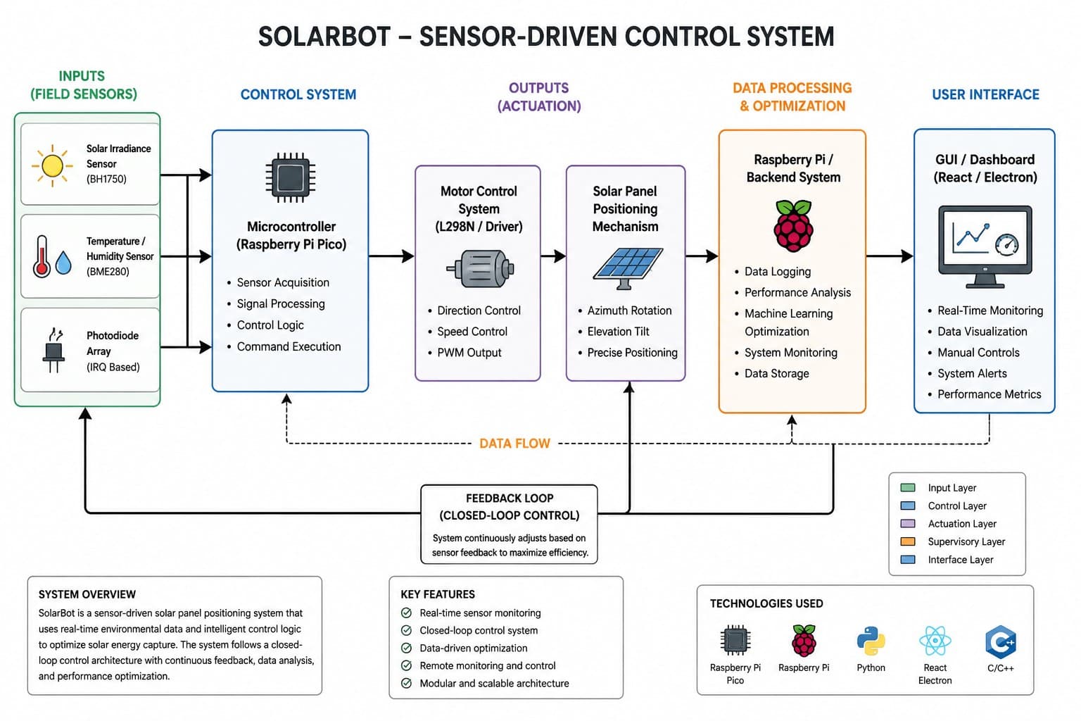
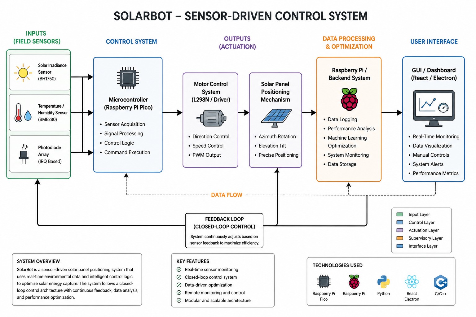
Telemetry can move from the physical prototype toward the interface; manual control returns through the same host boundary toward PWM and the pan/tilt mechanism.
- Physical prototype & partial sensingPanel, pan/tilt mechanism, sensor and integration work
- Pico / MicroPythonSensor reads, command handling, telemetry, PWM
- JSON / USB serialDevice-to-host transport boundary
- Raspberry Pi / FastAPIHost services, serial and application orchestration
- WebSocketTelemetry and operator-control transport
- React / ElectronConnection state, telemetry, and manual controls
Experimental / future supervisory layer
- ML / PSO explorationStatic-data research code; not connected to motor control
- MPPT / ANN researchFuture electrical-feedback direction after deterministic validation
One slider crosses the whole system.
The strongest verified technical story is manual control. I implemented a path from the React/MUI interface through WebSocket and serial transport to MicroPython command handling and physical pan/tilt actuation. I also used the interface to operate the mechanism. The timing values below describe command-pressure behavior in the code; they are not a measured end-to-end latency claim.
- React / MUI slider
- Latest-wins frontend throttle · ~80 ms
- WebSocket command
- FastAPI / host serial boundary
- MicroPython set_target handler
- Latest-wins firmware batch · ~50 ms
- MotionController target clamp · 0–180°
- PWM output
- User-confirmed pan / tilt movement
Integration created the real engineering challenge.
The work became a distributed systems problem as much as a mechanical one. It exposed state ownership, command pressure, asynchronous communication, timing, hardware/software boundaries, sensor integration, and failure handling as coupled design concerns.
- What improved
- The current source includes latest-wins throttling and firmware batching to prevent slider-generated command pressure from becoming a backlog.
- What remains visible
- Duplicate host serial ownership, blocking sensor collection, incomplete sensor integration, and unvalidated reconnect/recovery behavior remain active engineering tasks rather than hidden caveats.
Optimization is real research code, not live control.
SolarBot includes experimental work with Gradient Boosting, Random Forest, Isolation Forest, LIME, Particle Swarm Optimization, and physical power modeling. This is a promising future supervisory-control direction, but the current worker uses static snapshots and does not command the physical motor path.
Validation and next demonstration.
The next demonstration focuses on end-to-end validation: confirm sensor inputs, positioning response, telemetry visibility, and monitoring under controlled conditions. The presentation makes no quantified efficiency, travel-distance, or field-test claim.
- Not yet claimed
- No measured energy improvement, travel-distance result, field-test result, production-readiness claim, or verified command-latency metric is presented here.
- What comes after Demo V1
- Electrical power measurement, a fixed-panel baseline, deterministic tracking validation, and then electrical-feedback, MPPT, and lightweight learned optimization research.
Evidence before outcomes.
The project is presented through distinct evidence types: source-supported software architecture, direct confirmation of physical build and manual operation, experimental code separated from current capability, and explicit validation work still ahead. ART-015 and ART-016 are documented in the v0.3 packet but their source image files are not present in this portfolio workspace, so neither image is published here.